WARNING:
If you have been sent to this page while you are going to buy a jukebox and the seller told you the jukebox "has a small problem"
These jukeboxes are 50 years old. There are often no easy fixes. They need maintenance. Nobody will sell you a jukebox with a minor problem. They would fix it before selling it!
Trying to fix an old jukebox can be fun. But don't expect a quick solution.
You'lll need Electronical and mechanical skills. Problems can pop up while parts suddenly fail.
Do you want a reliable jukebox for years? Then it needs to be overhauled by an experienced NSM technician!
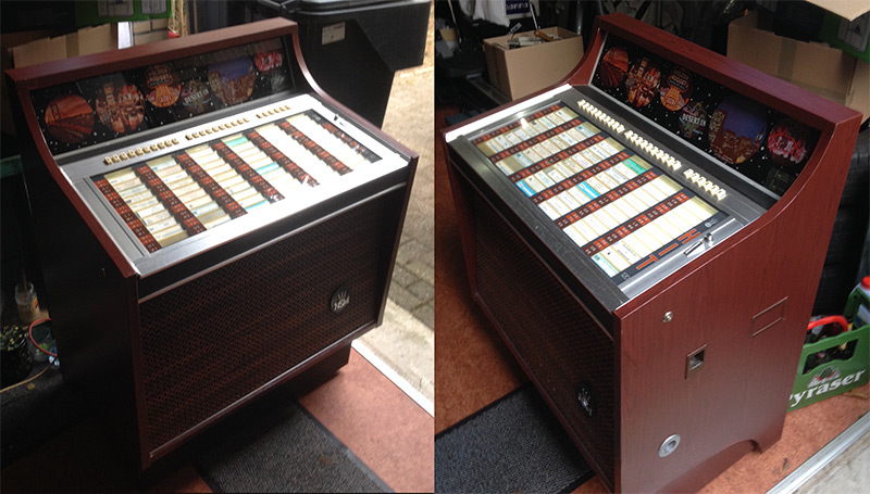
NSM jukebox Hit 120 from 1970
Detailed information about getting my jukebox Alive.
To the best of my knowledge, the information contained below is accurate and reliable as of the date of publication; however, I do not assume any liability whatsoever for the accuracy and completeness of the information on this page!

General Info
Year of production:1970
Total Weight: 95 kg
- Carriage base = 11 kg
- Phone chasis = 4 kg
- Amplifier 35M = 1 kg
- Central Unit with transformers = 6 kg
Dimension NSM HIT120: (Box)
- Height: 106 cm
- Width: 81 cm
- Depth: 58 cm
The Jukebox was in non working condition.
When the main 220v Switch on the back was put in upward position (=ON), nothing happened.
Even the lights did not turn on :)
But it was almost complete and the Box itself was in very good shape.
After close inspection I noticed:
- The light bulbs for coin selection where missing (24V, 3W)
- No MAIN fuse fitted (1,6A SLOW)
- Fitted AMPLIFIER fuse was blown (0,6A SLOW)
So I removed all plugs from the control center and installed a new 1,6A fuse.
The only plug I refitted was the 2B connector "Fluorescent-lamps".

Now the TL lamp and one of the two light bulbs behind the top glass switched on!
(There are 2 light bulbs behind the top glass, but it turned out the other light bulb was not fitted)
Next step was connecting the Amplifier 35M to connector 9B.
But the new fitted (0,65A Fast) fuse was blown immediately.
So something wrong there!
Part 1: NSM Amplifier 35M:
(pictures,schematics & part list are for 35M model 1970!)
Stickers inside the amp shows it has been repaired in december 1971 (sticker with initials) and a red "Inspected 1986" sticker.
Picture 1 - Repairs in the past
Picture 2 - 35M print & items before repairing

While checking (visual) all items on the print board I noticed some problems:
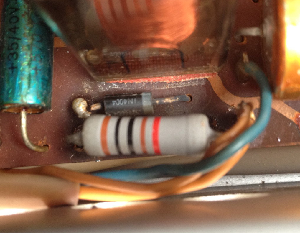
- Diode contact broken
- 2 poor elco's (one heavily damaged by hot solder iron)
- One wire not connected
- 1 burned resistor
Picture 3 - Diode broken: no contact with print.

After replacing/resoldering of these parts the fuse did not blow and the AMP worked!
Picture 4 - Testing the amplifier in original surrounding. It is connected to the Central Unit (plug 9B) and the original speakers.
Please notice I did not own the original Volume Control Unit so I connected a 10K potentiometer for testing purpose.
When testing, you should connect the amplifier chassis with jukebox earth.

But the sound quality (using seperate phono player with ceramic element) was poor.
The switches on the Amp to change bass/treble behaved strange.
Due to the state of many elkos I decided to replace all 25 elko's on the 35M circuit board.
With very good result: the sound quality improved much!
So if you are interested: below you will find the part list.
NSM 35M amplifier: Elko Replacement list:
C1 = 50 uF 16V
C3 = 1 uF 35V
C4 = 50 uF 15V
C5 = 50 uF 25V
C6 = 10 uF 63V (Fitted=63V, looks the original was 25V?)
C9 = 100 uF 3V
C10 = 250 uF 6V
C12 = 25 uF 10V
C13 = 25 uF 10V
C15 = 5 uF 35V
C16 = 10 uF 25V
C17 = 10 uF 25V
C18 = 50 uF 25V
C19 = 10 uF 25V
C20 = 100 uF 35V
C25 = 5 uF 35V
C30 = 250 uF 6V
C34 = 500 uF 35V
C35 = 5 uF 35V
C36 = 4,7 uF 35V (schematic:25 uF 10V)
C37 = 25 uF 35V
C39 = 50 uF 35V
C42 = 2500 uF 35V
C43 = 250 uF 6V
C80 = 2500 uF 70V
picture 5: 35M part list

R50 is for setting the output bias .
R15 is for adjusting the AVC .
how to setting the bias with ? you need to set it between 30 and 50 mA otherwise it will affect Sound overheat and cause other issues .
Which NSM Amplifier connects to phono element?
The HIT 120, (model 1970) should have 35M amplifier or 70S and MERULA DB200 element.
(The MERULA DB200 phone is a "Ceramic" element, SHURE is a "Magnetic Dynamic" element)
Working configurations, but not all original, for my HIT120 (1970)
- Amplifier: 35M & MERULA DB 200 (Ceramic element)
- Amplifier: 70S & MERULA DB 200 Amplifier: 70S & MERULA DB 200 (Ceramic element)
- Amplifier: 35M & SHURE (MD element): you need any (modern) DIN phono preamp
PART 2: Testing the Control Center / "Steuercentrale"
After connecting all connectors I turned on the jukebox.
The motor on the carriage was turning.
> But that is not what it should do when in stand by mode. It should be inactive.
Pressing the black "fahnknopf" on the scan control box" did not move the carriage to the left as it should when the jukebox is in 'stand by' mode.

To be sure I checked the fuses, but they where fine.
But when I touched some of the the connectors (plugged in the Control center) I could hear irregular relay switching and the motor turned off and on.
Definitely some connectors where not connected as they should.

So I checked the male connectors (to be plugged in) and some of the pins where loose or not making contact with the Female connectors on the Control Center.
After cleaning and repair of the loose pins and reconnecting them I turned on the Jukebox.
Now the motor on the carriage did not run! Perfect!
Touching the connectors didn't have effect anymore.
And after shortly pressing the "fahnknopf" the carriage moved to the left and at the end turned back to the starting position on the right. (stand by position)
That's exactly what it should do!
Would it work now?
I pressed the upper button on the coin mechanism to get some credit...
The mechanism in the credit box immediately answered with some clicking noises and the light in it turned on shortly.

So far so good but the carriage did not move.
And both selected buttons J & 4 stayed in the "down" position.
After turning off the jukebox (220v) the buttons returned to the "up" position like all other buttons.
After repeating these steps (Turning on jukebox, push credit, select record) I could hear the WA "START RELAY" switch after I pressed the second select record button.
So it looks like the buttons are working.
But the carriage should now move to the left to position of the selected record.
But it didn't.
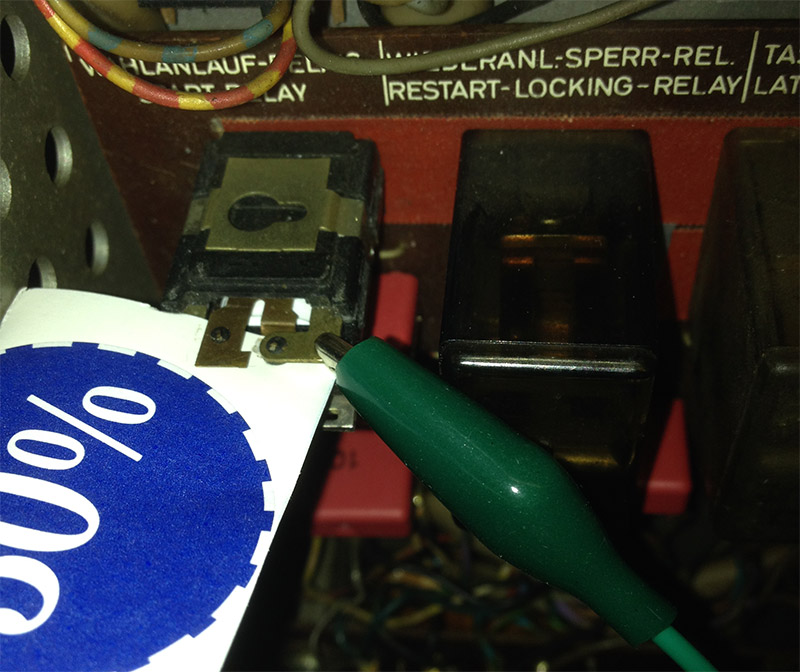
Checking the WA 'Start Relay' by watching it from close by (immedialely after making a selection on the keys), I noticed the electro magnet moves a small plate in the relay, but the contacts in the relay did not move at all. So it does not work as the relay should.
So I used a litte screwdriver and for a moment (<1 sec) to create a connection between the two relay contacts.
(normally done by the relay it self)
(on the picture I have connected two wires to the contacts on the WA relay to make testing easier, the other wire is invisble bur right below the wire with green isolation)


And yes, action!
The electromagnet in the defective relay was switched off and Immediately the motor in the scan control box started to rotate for a few seconds....
... and the carriage started to move to the left!
But would it pick up the record at Positition J4?!!
Unfortunately, it didn't.
It moved to the left, skipped J4, and at the end moved right back to start position. Then moved again to the full left and return back to the right 'stand by' position.
So the start relay is broken: but we have more problems: the carriage does not know where to stop. :(

Looking for info info on the web I noticed a lot of people having the same problem:
> The carriage moves to the left and back to the right without stopping and picking up the selected record.
This movie on youtube shows the same behavior as mine, this NSM Prestige 160 is technically close to the HIT 120 and there is an interesting comment by a guy "Roy":
https://www.youtube.com/watch?v=FbFp4digJ_Q
His comment:
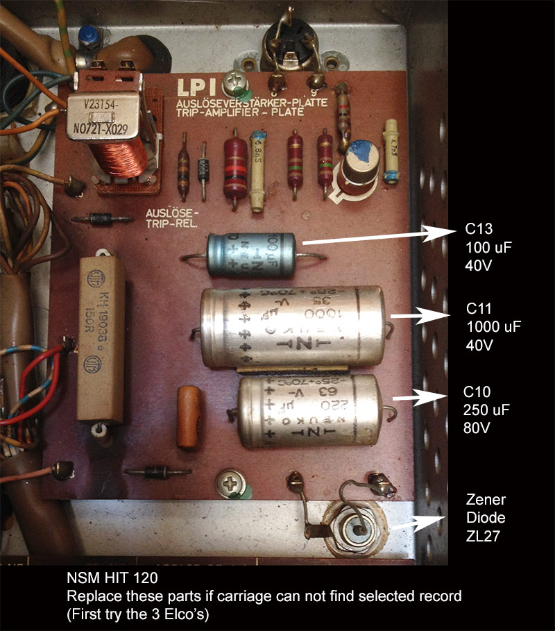
"Bad capacitors in the controlcenter. Replace them and if the problem is still not gone also replace the zenerdiode on LP1 also located in the controlcenter"
On a Dutch jukebox forum he aknowledged this advice: translated: "Do not fiddle with the contacts! Do not smooth them! Replace all elco's in the control center!"
And if you can read German, the same problem/solution described here: http://www.jukebox-world.de/Forum/Archiv/FAQ-NSM/Schlitten-hin-und-her.htm#3
Control Center: LPI Part List Trip Amplifier Plate:
C10= 250 uF 80V (fitted was a 220uF 63V)
C11= 1000 uF 40V
C13= 100 uF 40V
D16= silicium 400V
D17= silicium 400V
D18= silicium 400V
contact 1/2= zenerdiode ZL 27 :buy new one: https://www.jukebox-revival.eu/staging/zenerdiode-27-volt-voor-nsm-stuur-eenheid-selection-unit.html

update: New problem occurred
While testing there was smoke coming from the carriage...
I will have to investigate what is going on there. :(
Some info from the net (might be usefull)
Found this info on EBAY, maybe you can use it:
(don't know if it is 100% perfect information)
